

AVR环境:
编译环境: ubuntu + avr-gcc
烧写工具: avrdude+usbasp
具体构建步骤查看上一篇博客。
avr环境多种多样,在linux下还可以用eclipse集成环境。在window下推荐用WINAVR,其实本质上和linux下一样是用avr-gcc,烧写工具用prgisp.当然有了avr jtag仿真器就更好了,不用usbasp.
下载arduino工具:
arduino.cc/en/Main/Software
我下载的linux 64位版本,下载后解压到主目录下。
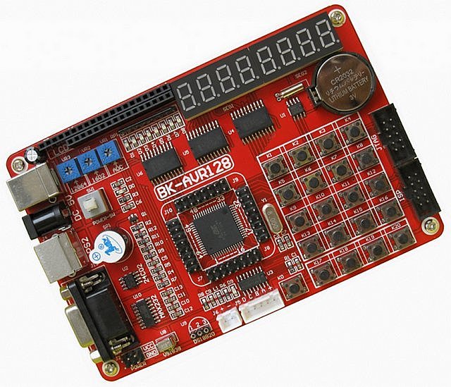
开发板:
BK-AVR128开发板
一、制作属于atmega128的bootloader
编译:
avr-gcc -mmcu=atmega48 -Wall -Os -o boot_mega128.o boot_mega128.c
avr-objcopy -j .text -j .data -O boot_mega128.o boot_mega.hex
烧写:
用usbasp连接电脑和开发板
sudo avrdude -p m128 -c usbasp -P usbasp -Uefuse:w:0xff:m -Uhfuse:w:0xca:m -Ulfuse:w:0xff:m -Ulock:w:0x3F:m
sudo avrdude -p m128 -c usbasp -e -U flash:w:boot_mega128.hex -Ulock:w:0x0F:m
二、Arduino开发环境设置
参考:
arduinoexplained.blogspot.com/2012/03/custom-board-programming-on-arduino-10.html
解压刚才下载的arduino
进入该目录
修改/hardware/arduino/avr/boards.txt
在最后添加:
<span style="font-size:14px;">###############################################################
atmega128A.name=Custom ATmega 128 Breakout Board using AVRISP
atmega128A.upload.using=avrispmkii
atmega128A.upload.maximum_size=126976
atmega128A.bootloader.low_fuses=0xFF
atmega128A.bootloader.high_fuses=0xCA
atmega128A.bootloader.extended_fuses=0xFF
atmega128A.bootloader.path=atmega
atmega128A.bootloader.file=boot_mega128.hex
atmega128A.bootloader.unlock_bits=0x3F
atmega128A.bootloader.lock_bits=0x0F
atmega128A.build.mcu=atmega128
atmega128A.build.f_cpu=8000000L
atmega128A.build.core=arduino
atmega128A.build.variant=standard


##############################################################</span>
三、设置arduino引脚定义
在网上没有找到atmega128的arduino pin mapping,于是自己写了一个
在/hardware/arduino/avr/variant文件夹下新建一个文件夹mega128
在mega128里面新建一个pins_arduino.h
/*
  pins_arduino.h - Pin definition functions for Arduino ATmega128
  Part of Arduino - http://blog.csdn.net/canyue102/article/details/9451771

  Copyright (c) 2013 Dongyu_canyue102

  This library is free software; you can redistribute it and/or
  modify it under the terms of the GNU Lesser General Public
  License as published by the Free Software Foundation; either
  version 2.1 of the License, or (at your option) any later version.

*/

#ifndef Pins_Arduino_h
#define Pins_Arduino_h

#include <avr/pgmspace.h>

#define NUM_DIGITAL_PINS            53
#define NUM_ANALOG_INPUTS           8
#define analogInputToDigitalPin(p)  ((p < 8) ? (p) + 45 : -1)
#define digitalPinHasPWM(p)         (((p) >= 12 && (p) <= 15) || ((p) >= 35 && (p)<= 37))

static const uint8_t SS   = 8;
static const uint8_t MOSI = 10;
static const uint8_t MISO = 11;
static const uint8_t SCK  = 9;

static const uint8_t SDA = 25;
static const uint8_t SCL = 24;
static const uint8_t LED_BUILTIN = 12;

static const uint8_t A0 = 40;
static const uint8_t A1 = 41;
static const uint8_t A2 = 42;
static const uint8_t A3 = 43;
static const uint8_t A4 = 44;
static const uint8_t A5 = 45;
static const uint8_t A6 = 46;
static const uint8_t A7 = 47;

// A majority of the pins are NOT PCINTs, SO BE WARNED (i.e. you cannot use them as receive pins)
// Only pins available for RECEIVE (TRANSMIT can be on any pin):
// (I've deliberately left out pin mapping to the Hardware USARTs - seems senseless to me)
// Pins: 0-53

#define digitalPinToPCICR(p)    (((p) >= 0 && (p) <= 53) ? (&PCICR) : ((uint8_t *)0))

#define digitalPinToPCICRbit(p) ( (((p) >= 0) && ((p) <= 7)) || (((p) >= 8) && ((p) <=47 )) ? 0 :
                                ( (((p) >= 48) && ((p) <= 52)) ? 2 :
                                0 ) )

#define digitalPinToPCMSK(p)    ( (((p) >= 0) && ((p) <= 7)) || (((p) >= 8) && ((p) <= 47)) ? (&PCMSK0) :
                                ( (((p) >= 48) && ((p) <= 52)) ? (&PCMSK2) :
                                ((uint8_t *)0) ) )

#define digitalPinToPCMSKbit(p) ( (((p) >= 0) && ((p) <= 7)) ? ((p) - 6) :
                                ( ((p) == 8) ? 3 :
                                ( ((p) == 9) ? 2 :
                                ( ((p) == 10) ? 1 :
                                ( ((p) == 11) ? 0 :
                                ( (((p) >= 12) && ((p) <= 52)) ? ((p) - 12) :
                                0 ) ) ) ) ) )

#ifdef ARDUINO_MAIN

const uint16_t PROGMEM port_to_mode_PGM[] = {
	NOT_A_PORT,
	(uint16_t) &DDRA,
	(uint16_t) &DDRB,
	(uint16_t) &DDRC,
	(uint16_t) &DDRD,
	(uint16_t) &DDRE,
	(uint16_t) &DDRF,
	(uint16_t) &DDRG,

};

const uint16_t PROGMEM port_to_output_PGM[] = {
	NOT_A_PORT,
	(uint16_t) &PORTA,
	(uint16_t) &PORTB,
	(uint16_t) &PORTC,
	(uint16_t) &PORTD,
	(uint16_t) &PORTE,
	(uint16_t) &PORTF,
	(uint16_t) &PORTG,

};

const uint16_t PROGMEM port_to_input_PGM[] = {
	NOT_A_PIN,
	(uint16_t) &PINA,
	(uint16_t) &PINB,
	(uint16_t) &PINC,
	(uint16_t) &PIND,
	(uint16_t) &PINE,
	(uint16_t) &PINF,
	(uint16_t) &PING,

};

const uint8_t PROGMEM digital_pin_to_port_PGM[] = {
	// PORTLIST
	// -------------------------------------------
        PA	, // PA 0 ** 0 ** D22
	PA	, // PA 1 ** 1 ** D23
	PA	, // PA 2 ** 2 ** D24
	PA	, // PA 3 ** 3 ** D25
	PA	, // PA 4 ** 4 ** D26
	PA	, // PA 5 ** 5 ** D27
	PA	, // PA 6 ** 6 ** D28
	PA	, // PA 7 ** 7 ** D29
	PB	, // PB 0 ** 8 ** SPI_MISO
	PB	, // PB 1 ** 9 ** SPI_MOSI
	PB	, // PB 2 ** 10 ** SPI_SCK
	PB	, // PB 3 ** 11 ** SPI_SS
	PB	, // PB 4 ** 12 ** PWM10
	PB	, // PB 5 ** 13 ** PWM11
	PB	, // PB 6 ** 14 ** PWM12
	PB	, // PB 7 ** 15 ** PWM13
	PC	, // PC 0 ** 16 ** D30
	PC	, // PC 1 ** 17 ** D31
	PC	, // PC 2 ** 18 ** D32
	PC	, // PC 3 ** 19 ** D33
	PC	, // PC 4 ** 20 ** D34
	PC	, // PC 5 ** 21 ** D35
	PC	, // PC 6 ** 22 ** D36
	PC	, // PC 7 ** 23 ** D37
        PD	, // PD 0 ** 24 ** USART1_TX
	PD	, // PD 1 ** 25 ** USART1_RX
	PD	, // PD 2 ** 26 ** I2C_SDA
	PD	, // PD 3 ** 27 ** I2C_SCL
	PD	, // PD 4 ** 28 ** D38
	PD	, // PD 5 ** 29 ** I2C_SDA
	PD	, // PD 6 ** 30 ** I2C_SCL
	PD	, // PD 7 ** 31 ** D38
	PE	, // PE 0 ** 32 ** USART0_RX
	PE	, // PE 1 ** 33 ** USART0_TX
	PE	, // PE 2 ** 34 ** PWM2
	PE	, // PE 3 ** 35 ** PWM3
	PE	, // PE 4 ** 36 ** PWM5
	PE	, // PE 5 ** 37 ** PWM2
	PE	, // PE 6 ** 38 ** PWM3
	PE	, // PE 7 ** 39 ** PWM5
        PF	, // PF 0 ** 40 ** A0
	PF	, // PF 1 ** 41 ** A1
	PF	, // PF 2 ** 42 ** A2
	PF	, // PF 3 ** 43 ** A3
	PF	, // PF 4 ** 44 ** A4
	PF	, // PF 5 ** 45 ** A5
	PF	, // PF 6 ** 46 ** A6
	PF	, // PF 7 ** 47 ** A7
	PG	, // PG 0 ** 48 ** D39
	PG	, // PG 1 ** 49 ** D40
	PG	, // PG 2 ** 50 ** D41
	PG	, // PG 3 ** 51 ** D41
        PG	, // PG 4 ** 52 ** D41
};

const uint8_t PROGMEM digital_pin_to_bit_mask_PGM[] = {
	// PIN IN PORT
	// -------------------------------------------
	_BV( 0 )	, // PA 0 ** 22 ** D22
	_BV( 1 )	, // PA 1 ** 23 ** D23
	_BV( 2 )	, // PA 2 ** 24 ** D24
	_BV( 3 )	, // PA 3 ** 25 ** D25
	_BV( 4 )	, // PA 4 ** 26 ** D26
	_BV( 5 )	, // PA 5 ** 27 ** D27
	_BV( 6 )	, // PA 6 ** 28 ** D28
	_BV( 7 )	, // PA 7 ** 29 ** D29
        _BV( 0 )	, // PB 3 ** 50 ** SPI_MISO
	_BV( 1 )	, // PB 2 ** 51 ** SPI_MOSI
	_BV( 2 )	, // PB 1 ** 52 ** SPI_SCK
	_BV( 3 )	, // PB 0 ** 53 ** SPI_SS
	_BV( 4 )	, // PB 4 ** 10 ** PWM10
	_BV( 5 )	, // PB 5 ** 11 ** PWM11
	_BV( 6 )	, // PB 6 ** 12 ** PWM12
	_BV( 7 )	, // PB 7 ** 13 ** PWM13
        _BV( 0 )	, // PC 7 ** 30 ** D30
	_BV( 1 )	, // PC 6 ** 31 ** D31
	_BV( 2 )	, // PC 5 ** 32 ** D32
	_BV( 3 )	, // PC 4 ** 33 ** D33
	_BV( 4 )	, // PC 3 ** 34 ** D34
	_BV( 5 )	, // PC 2 ** 35 ** D35
	_BV( 6 )	, // PC 1 ** 36 ** D36
	_BV( 7 )	, // PC 0 ** 37 ** D37
        _BV( 0 )	, // PD 3 ** 18 ** USART1_TX
	_BV( 1 )	, // PD 2 ** 19 ** USART1_RX
	_BV( 2 )	, // PD 1 ** 20 ** I2C_SDA
	_BV( 3 )	, // PD 0 ** 21 ** I2C_SCL
	_BV( 4 )	, // PD 3 ** 18 ** USART1_TX
	_BV( 5 )	, // PD 2 ** 19 ** USART1_RX
	_BV( 6 )	, // PD 1 ** 20 ** I2C_SDA
	_BV( 7 )	, // PD 0 ** 21 ** I2C_SCL
	_BV( 0 )	, // PE 0 ** 0 ** USART0_RX
	_BV( 1 )	, // PE 1 ** 1 ** USART0_TX
	_BV( 2 )	, // PE 4 ** 2 ** PWM2
	_BV( 3 )	, // PE 5 ** 3 ** PWM3
	_BV( 4 )	, // PE 0 ** 0 ** USART0_RX
	_BV( 5 )	, // PE 1 ** 1 ** USART0_TX
	_BV( 6 )	, // PE 4 ** 2 ** PWM2
	_BV( 7 )	, // PE 5 ** 3 ** PWM3
	_BV( 0 )	, // PF 0 ** 54 ** A0
	_BV( 1 )	, // PF 1 ** 55 ** A1
	_BV( 2 )	, // PF 2 ** 56 ** A2
	_BV( 3 )	, // PF 3 ** 57 ** A3
	_BV( 4 )	, // PF 4 ** 58 ** A4
	_BV( 5 )	, // PF 5 ** 59 ** A5
	_BV( 6 )	, // PF 6 ** 60 ** A6
	_BV( 7 )	, // PF 7 ** 61 ** A7
	_BV( 0 )	, // PG 0 ** 62 ** A8
	_BV( 1 )	, // PG 1 ** 63 ** A9
	_BV( 2 )	, // PG 2 ** 64 ** A10
	_BV( 3 )	, // PG 3 ** 65 ** A11
	_BV( 4 )	, // PG 4 ** 66 ** A12

};

const uint8_t PROGMEM digital_pin_to_timer_PGM[] = {
	// TIMERS
	// -------------------------------------------
	NOT_ON_TIMER	, // PA 0 ** 22 ** D22
	NOT_ON_TIMER	, // PA 1 ** 23 ** D23
	NOT_ON_TIMER	, // PA 2 ** 24 ** D24
	NOT_ON_TIMER	, // PA 3 ** 25 ** D25
	NOT_ON_TIMER	, // PA 4 ** 26 ** D26
	NOT_ON_TIMER	, // PA 5 ** 27 ** D27
	NOT_ON_TIMER	, // PA 6 ** 28 ** D28
	NOT_ON_TIMER	, // PA 7 ** 29 ** D29
	NOT_ON_TIMER	, // PB 0 ** 13 ** PWM13
	NOT_ON_TIMER	, // PB 1 ** 50 ** SPI_MISO
	NOT_ON_TIMER	, // PB 2 ** 51 *7* SPI_MOSI
	NOT_ON_TIMER	, // PB 3 ** 52 ** SPI_SCK
	TIMER0A	, // PB 4 ** 53 ** SPI_SS
 	TIMER1A	, // PB 5 ** 10 ** PWM10
	TIMER1B	, // PB 6 ** 11 ** PWM11
	TIMER2A	, // PB 7 ** 12 ** PWM12
	NOT_ON_TIMER	, // PC 0 ** 30 ** D30
	NOT_ON_TIMER	, // PC 1 ** 31 ** D31
	NOT_ON_TIMER	, // PC 2 ** 32 ** D32
	NOT_ON_TIMER	, // PC 3 ** 33 ** D33
	NOT_ON_TIMER	, // PC 4 ** 34 ** D34
	NOT_ON_TIMER	, // PC 5 ** 35 ** D35
	NOT_ON_TIMER	, // PC 6 ** 36 ** D36
	NOT_ON_TIMER	, // PC 7 ** 37 ** D37
        NOT_ON_TIMER	, // PD 0 ** 18 ** USART1_TX
	NOT_ON_TIMER	, // PD 1 ** 19 ** USART1_RX
	NOT_ON_TIMER	, // PD 2 ** 20 ** I2C_SDA
	NOT_ON_TIMER	, // PD 3 ** 21 ** I2C_SCL
	NOT_ON_TIMER	, // PD 4 ** 19 ** USART1_RX
	NOT_ON_TIMER	, // PD 5 ** 20 ** I2C_SDA
	NOT_ON_TIMER	, // PD 6 ** 21 ** I2C_SCL
	NOT_ON_TIMER	, // PD 7 ** 21 ** I2C_SCL
	NOT_ON_TIMER	, // PE 0 ** 0 ** USART0_RX
	NOT_ON_TIMER	, // PE 1 ** 1 ** USART0_TX
	NOT_ON_TIMER	, // PE 2 ** 2 ** PWM2
	TIMER3A	, // PE 3 ** 3 ** PWM3
	TIMER3B	, // PE 4 ** 0 ** USART0_RX
	TIMER3C	, // PE 5 ** 1 ** USART0_TX
	NOT_ON_TIMER	, // PE 6 ** 2 ** PWM2
	NOT_ON_TIMER	, // PE 7 ** 3 ** PWM3
	NOT_ON_TIMER	, // PG 0 ** 39 ** D39
	NOT_ON_TIMER	, // PG 1 ** 40 ** D40
	NOT_ON_TIMER	, // PG 2 ** 41 ** D41
	NOT_ON_TIMER 	, // PG 3 ** 4 ** PWM4
	NOT_ON_TIMER	, // PG 4 ** 41 ** D41
};

#endif

#endif
再将boards.txt的
atmega128A.build.variant=standard
改为
atmega128A.build.variant=mega128
| arduino io | 主芯片 IO 口 | 外部资源 1 | 外部资源 2 | 外部资源 3 | 外部资源 4 |
| 0 | PA0/A/D0 | 流水灯(D1) | 数码管(位 1) | LCD1602(D0) | LCD12864(D0) |
| 1 | PA1 | 流水灯(D2) | 数码管(位 2) | LCD1602(D1) | LCD12864(D1) |
| 2 | PA2 | 流水灯(D3) | 数码管(位 3) | LCD1602(D2) | LCD12864(D2) |
| 3 | PA3 | 流水灯(D4) | 数码管(位 4) | LCD1602(D3) | LCD12864(D3) |
| 4 | PA4 | 流水灯(D5) | 数码管(位 5) | LCD1602(D4) | LCD12864(D4) |
| 5 | PA5 | 流水灯(D6) | 数码管(位 6) | LCD1602(D5) | LCD12864(D5) |
| 6 | PA6 | 流水灯(D7) | 数码管(位 7) | LCD1602(D6) | LCD12864(D6) |
| 7 | PA7 | 流水灯(D8) | 数码管(位 8) | LCD1602(D7) | LCD12864(D7) |
| 8 | PB0/SS | 步进电机 | |||
| 9 | PB1/SCK | 步进电机 | |||
| 10 | PB2/MOSI | 步进电机 | |||
| 11 | PB3/MISO | 步进电机 | |||
| 12 | PB4/OC0 | 直流电机 | PWM(D9) | ||
| 13 | PB5/OC1A | LCD1602(RS) | LCD12864(RS) | ||
| 14 | PB6/OC1B | LCD1602(RW) | LCD12864 | ||
| 15 | PB7/OC1C | LCD1602(EN) | (RW) | ||
| 16 | PC0/A8 | 数码管(段 A) | LCD12864(EN) | ||
| 17 | PC1 | 数码管(段 B) | |||
| 18 | PC2 | 数码管(段 C) | |||
| 19 | PC3 | 数码管(段 D) | |||
| 20 | PC4 | 数码管(段 E) | |||
| 21 | PC5 | 数码管(段 F) | |||
| 22 | PC6 | 数码管(段 G) | |||
| 23 | PC7 | 数码管(段 dp) | |||
| 24 | PD0/SCL/INT0 | 矩阵键盘(行 1) | 按键 K17 | AT24C02(SCL) | |
| 25 | PD1/SDA/INT1 | 矩阵键盘(行 2) | 按键 K18 | AT24C02(SDA) | |
| 26 | PD2/RXD1/INT2 | 矩阵键盘(行 3) | 按键 K110 | PSII(DAT) | 红外线接收 |
| 27 | PD3/TXD1/INT3 | 矩阵键盘(行 4) | 按键 K20 | PSII(CLK) | |
| 28 | PD4/ICP1 | 矩阵键盘(列 1) | |||
| 29 | PD5/XCK1 | 矩阵键盘(列 2) | |||
| 30 | PD6/T1 | 矩阵键盘(列 3) | |||
| 31 | PD7/T2 | 矩阵键盘(列 4) | |||
| 32 | PE0/RXD0/PDI | 串口(RXD) | |||
| 33 | PE1/TXD0/PDO | 串口(TXD) | |||
| 34 | PE2/XCK0/AIN0 | DS1302(SCLK) | |||
| 35 | PE3/OC3A/AIN1 | DS1302(I/0) | |||
| 36 | PE4/OC3B/INT4 | DS1302(RST) | |||
| 37 | PE5/OC3C/INT5 | 空闲 | |||
| 38 | PE6/T3/INT6 | DS18B20 | |||
| 39 | PE7/ICP3/INT7 | 蜂鸣器 | |||
| 40 | PF0/ADC0 | ADC 输入 | |||
| 41 | PF1/ADC1 | 数码管段选锁存 | |||
| 42 | PF2 | 数码管位选锁存 | |||
| 43 | PF3 | 流水灯锁存 | |||
| 44 | PF4 | JTAG(TCK) | |||
| 45 | PF5 | JTAG(TMS) | |||
| 46 | PF6 | JTAG(TDO) | |||
| 47 | PF7 | JTAG(TDI) | |||
| 48 | PG0/WR | 空闲 | |||
| 49 | PG1/RD | 空闲 | |||
| 50 | PG2/ALE | 空闲 | |||
| 51 | PG3/TOSC2 | 空闲 | |||
| 52 | PG4/TOSC2 | 空闲 |
四、 最后启动arduino开发环境:
sudo ./arduino
测试程序:
int ledPin =12;
void setup() {
// put your setup code here, to run once:
pinMode(ledPin,OUTPUT);
}
void loop() {
// put your main code here, to run repeatedly:
digitalWrite(ledPin,HIGH);
delay(1000);
digitalWrite(ledPin,LOW);
delay(1000);
}
点击upload则在开发板上开始一个一闪一闪的led。第12pin是PB4开发板上正好对应一个LED。
好吧,可是开始arduino的开发之旅了。要学好arduino还是要花很多精力和时间的。


不错
加油
很好很好很好 加油努力 你可以的
感谢分享!