简介:micropython-fusion传感器融合从运动跟踪设备的输出计算航向、俯仰和横滚。该算法使用了Madgwick算法,由于其速度和质量,在多机设计中得到了广泛的应用。在Pyboard上更新需要不到2mS的时间。最初的Madgwick研究表明,10-50Hz的更新速率足以获得准确的结果,这表明该实现的性能足够快。提供了两种实现:一种用于同步代码,另一种用于基于asyncio的异步应用程序。
Platforms
This document describes the case where sensor data is acquired, and fusion is performed, on a single platform running MicroPython.
Other modes are supported:
- Fusion and data acquisition run on a common device under standard Python.
- Fusion and data acquisition run on separate devices linked by some form of communications link. In this mode the data acquisition device may run any type of code and return data in any format, with the user application reading and converting the data to a form acceptable to the library.
These modes are discussed here.
MicroPython issues
The code is intended to be independent of the sensor device: testing was done with the InvenSense MPU-9150.
The algorithm makes extensive use of floating point maths. Under MicroPython this implies RAM allocation. While the code is designed to be platform agnostic problems may be experienced on platforms with small amounts of RAM. Options are to use frozen bytecode and to periodically run a garbage collection; the latter is advisable even on the Pyboard. See the fusionlcd.py test program for an example of this.
Terminology and units of measurement
I should point out that I’m unfamiliar with aircraft conventions and would appreciate feedback if the following observations about coordinate conventions are incorrect.
Angles
Inertial measurement units (IMU’s) exist with and without magnetometers. Those with them are known as 9DOF, and those without as 6DOF sensors where DOF stands for “degrees of freedom”. 6DOF sensors cannot provide heading information as this is derived with reference to the Earth’s magnetic field.
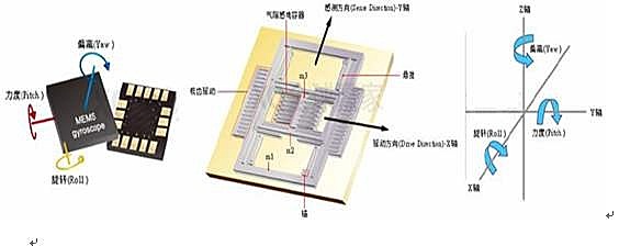
The object of sensor fusion is to determine a vehicle’s attitude with respect to Earth. This is expressed in the following three angles:
headingAngle relative to North. Note some sources use the term “yaw”. As this is also used to mean the angle of an aircraft’s fuselage relative to its direction of motion, I have avoided it.pitchAngle of aircraft nose relative to ground (conventionally +ve is towards ground). Also known as “elevation”.rollAngle of aircraft wings to ground, also known as “bank”.
In this implementation these are measured in degrees.
Sensors
The units of measurement provided by the sensor driver are important only in the case of the gyroscope. This must provide a measurement in degrees per second. Values from the accelerometer (typically g) and the magnetometer (typically Microtesla) are normalised in the algorithm. This uses the fact that the magnitude of these vectors is locally constant; consequently the units of measurement are irrelevant.
The issue of the orientation of the sensor is discussed in section 4.
Contents
2.1 Fusion class
2.1.1 Methods
2.1.2 Bound variables
3.1 Fusion class
3.1.1 Methods
3.1.2 Variables
5.2 Beta
1. Modules
fusion.pyThe standard synchronous fusion library.fusion_async.pyVersion of the library using uasyncio for nonblocking access to pitch, heading and roll.deltat.pyControls timing for above.orientate.pyA utility for adjusting orientation of an IMU for sensor fusion.
Test/demo programs:
fusiontest.pyA simple test program for synchronous library.fusiontest6.pyVariant of above for 6DOF sensors.fusiontest_as.pySimple test for the asynchronous library.fusiontest_as6.pyVariant of above for 6DOF sensors.fusionlcd.pyTests the async library with a Hitachi HD44780 2-row LCD text display to continuously display angle values.
The directory remote contains files and information specific to remote mode and to running fusion on standard Python.
Jump to Contents
2. Fusion module
2.1 Fusion class
The module supports this one class. A Fusion object needs to be periodically updated with data from the sensor. It provides heading, pitch and roll values (in degrees) as properties. Note that if you use a 6DOF sensor, heading will be invalid.
2.1.1 Methods
update(accel, gyro, mag)
For 9DOF sensors. Positional arguments:
accelA 3-tuple (x, y, z) of accelerometer data.gyroA 3-tuple (x, y, z) of gyro data.magA 3-tuple (x, y, z) of magnetometer data.
This method should be called periodically at a frequency depending on the required response speed.
update_nomag(accel, gyro)
For 6DOF sensors. Positional arguments:
accelA 3-tuple (x, y, z) of accelerometer data.gyroA 3-tuple (x, y, z) of gyro data.
This should be called periodically, depending on the required response speed.
calibrate(getxyz, stopfunc, wait=0)
Positional arguments:
getxyzA function returning a 3-tuple of magnetic x,y,z values.stopfuncA function returningTruewhen calibration is deemed complete: this could be a timer or an input from the user.waitA delay in ms. Some hardware may require a delay between magnetometer readings. Alternatively a function which returns after a delay may be passed.
Calibration updates the magbias bound variable. It is performed by rotating the unit slowly around each orthogonal axis while the routine runs, the aim being to compensate for offsets caused by static local magnetic fields.
2.1.2 Bound variables
Three bound variables provide access to the angles in degrees:
headingpitchroll
A bound variable beta controls algorithm performance. The default value may be altered after instantiation. See section 5.2.
A class variable declination, defaulting to 0, enables the heading to be offset in order to provide readings relative to true North rather than magnetic North. A positive value adds to heading.
Jump to Contents
3. Asynchronous version
This uses the uasyncio library and is intended for applications based on asynchronous programming. Updates are performed by a continuously running coroutine. The heading, pitch and roll values are bound variables which may be accessed at any time with effectively zero latency. The test program fusionlcd.py illustrates its use showing realtime data on a text LCD display, fusiontest_as.py prints it at the REPL.
3.1 Fusion class
The module supports this one class. The constructor is passed a user-supplied coro which returns the accelerometer, gyro, and (in the case of 9DOF sensors) magnetometer data. A Fusion instance has a continuously running coroutine which maintains the heading, pitch and roll bound variables.
Typical constructor call:
imu = MPU9150('X')  # Instantiate IMU (default orientation)

async def read_coro():
    imu.mag_trigger()  # Hardware dependent: trigger a nonblocking readawait asyncio.sleep_ms(20)  # Wait for mag to be readyreturn imu.accel.xyz, imu.gyro.xyz, imu.mag_nonblocking.xyz# Returned (ax, ay, az), (gx, gy, gz), (mx, my, mz)

fuse = Fusion(read_coro)
The update method is started as follows (usually, in the case of 9DOF sensors, after a calibration phase):
await fuse.start()
This starts a continuously running update task. It calls the coro supplied to the constructor to determine (from the returned data) whether the sensor is a 6DOF or 9DOF variety. It then launches the appropriate task. From this point the application accesses the heading, pitch and roll bound variables as required.
3.1.1 Methods
Constructor:
This takes a single argument which is a coroutine. This returns three (x, y, z) 3-tuples for accelerometer, gyro, and magnetometer data respectively. In the case of 6DOF sensors it returns two 3-tuples for accelerometer and gyro only. The coroutine must include at least one await asyncio.sleep_ms statement to conform to Python syntax rules. A nonzero delay may be required by the IMU hardware; it may also be employed to limit the update rate, thereby controlling the CPU resources used by this task.
async def start(slow_platform=False)
This launches the update task, returning immediately.
Optional argument:
slow_platformBoolean. Adds a yield to the scheduler in the middle of the computation. This may improve application performance on slow platforms such as the ESP8266.
async def calibrate(stopfunc)
For 9DOF sensors only.
Argument:
stopfuncFunction returningTruewhen calibration is deemed complete: this could be a timer or an input from the user.
Calibration updates the magbias bound variable. It is performed by rotating the unit slowly around each orthogonal axis while the routine runs, the aim being to compensate for offsets caused by static local magnetic fields.
3.1.2 Variables
Three bound variables provide the angles with negligible latency. Units are degrees.
headingpitchroll
A bound variable beta controls algorithm performance. The default value may be altered after instantiation. See section 5.2.
A class variable declination, defaulting to 0, enables the heading to be offset in order to provide readings relative to true North rather than magnetic North. A positive value adds to heading.
Jump to Contents
4. Notes for constructors
If you’re developing a machine using a motion sensing device consider the effects of vibration. This can be surprisingly high (use the sensor to measure it). No amount of digital filtering will remove it because it is likely to contain frequencies above the sampling rate of the sensor: these will be aliased down into the filter passband and affect the results. It’s normally necessary to isolate the sensor with a mechanical filter, typically a mass supported on very soft rubber mounts.
If using a magnetometer consider the fact that the Earth’s magnetic field is small: the field detected may be influenced by ferrous metals in the machine being controlled or by currents in nearby wires. If the latter are variable there is little chance of compensating for them, but constant magnetic offsets may be addressed by calibration. This involves rotating the machine around each of three orthogonal axes while running the fusion object’s calibrate method.
The local coordinate system for the sensor is usually defined as follows, assuming the vehicle is on the ground:
z Vertical axis, vector points towards ground
x Axis towards the front of the vehicle, vector points in normal direction of travel
y Vector points left from pilot’s point of view (I think)
orientate.py has some simple code to correct for sensors mounted in ways which don’t conform to this convention.
You may want to take control of garbage collection (GC). In systems with continuously running control loops there is a case for doing an explicit GC on each iteration: this tends to make the GC time shorter and ensures it occurs at a predictable time. See the MicroPython gc module.
Jump to Contents
5. Background notes
These are blatantly plagiarised as this isn’t my field. I have quoted sources.
5.1 Heading Pitch and Roll
Perhaps better titled heading, elevation and bank: there seems to be ambiguity about the concept of yaw, whether this is measured relative to the aircraft’s local coordinate system or that of the Earth: the original Madgwick study uses the term “heading”, a convention I have retained as the angles emitted by the Madgwick algorithm (Tait-Bryan angles) are earth-relative.
The following adapted from https://github.com/kriswiner/MPU-9250.git
These are Tait-Bryan angles, commonly used in aircraft orientation (DIN9300). In this coordinate system the positive z-axis is down toward Earth. Yaw is the angle between Sensor x-axis and Earth magnetic North (or true North if corrected for local declination). Looking down on the sensor positive yaw is counter-clockwise. Pitch is angle between sensor x-axis and Earth ground plane, aircraft nose down toward the Earth is positive, up toward the sky is negative. Roll is angle between sensor y-axis and Earth ground plane, y-axis up is positive roll. These arise from the definition of the homogeneous rotation matrix constructed from quaternions. Tait-Bryan angles as well as Euler angles are non-commutative; that is, the get the correct orientation the rotations must be applied in the correct order which for this configuration is yaw, pitch, and then roll. For more see Wikipedia article which has additional links.
I have seen sources which contradict the above directions for yaw (heading) and roll (bank).
5.2 Beta
The Madgwick algorithm has a “magic number” Beta which determines the tradeoff between accuracy and response speed.
Source of comments below.
There is a tradeoff in the beta parameter between accuracy and response speed. In the original Madgwick study, beta of 0.041 (corresponding to GyroMeasError of 2.7 degrees/s) was found to give optimal accuracy. However, with this value, the LSM9SD0 response time is about 10 seconds to a stable initial quaternion. Subsequent changes also require a longish lag time to a stable output, not fast enough for a quadcopter or robot car! By increasing beta (GyroMeasError) by about a factor of fifteen, the response time constant is reduced to ~2 sec. I haven’t noticed any reduction in solution accuracy. This is essentially the I coefficient in a PID control sense; the bigger the feedback coefficient, the faster the solution converges, usually at the expense of accuracy. In any case, this is the free parameter in the Madgwick filtering and fusion scheme.