


从Wemos D1 mini到NodeMCU,基于ESP8266的板是低成本和普遍易用的,是迄今为止在制造商和爱好者中最受欢迎的平台,用于构建基于WiFi的项目。在今天的教程中,我们将继续探索最流行的基于ESP8266的开发板。在NodeMCU开发板,我们将探讨如何使用它来建立一个Web服务器。通过Web服务器,我们将能够控制连接到板的GPIO引脚的任何东西。我们将不仅仅局限于控制LED,而是通过扩展该项目,您可以构建成熟的家庭自动化系统或任何其他涉及从NodeMCU的GPIO远程控制或获取数据的项目。
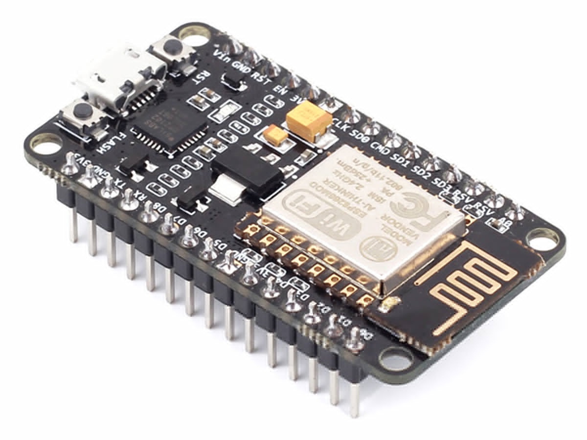
NodeMCU开发板
NodeMCU开发板是用于开发基于WiFi的嵌入式设备的开源平台。它基于ESP8266 WiFi模块并运行基于Lua的NodeMCU固件。NodeMCU的诞生是为了克服与ESP8266模块第一版相关的所有瓶颈,该版本与面包板不兼容,难以供电,甚至更难编程。它的易用性和低成本使其迅速受到制造商的青睐,并且是当今最受欢迎的主板之一。在本教程的最后,您将知道如何将NodeMCU用作Web服务器,以及如何从网页控制NodeMCU / ESP8266板的GPIO引脚。
所需组件
构建此项目需要以下组件;
- NodeMCU(ESP8266-12E)
- 220欧姆电阻器(2)
- LED灯(2)
- 面包板
- 杜邦线
- 原理图
该项目的原理图非常简单。如前所述,我们将切换LED来演示使用NodeMCU Web服务器可以实现的目标。在这里使用LED时,您可以决定使用更有用的组件,例如继电器,然后可以将其用于控制家庭中的电器。如下图所示连接组件。
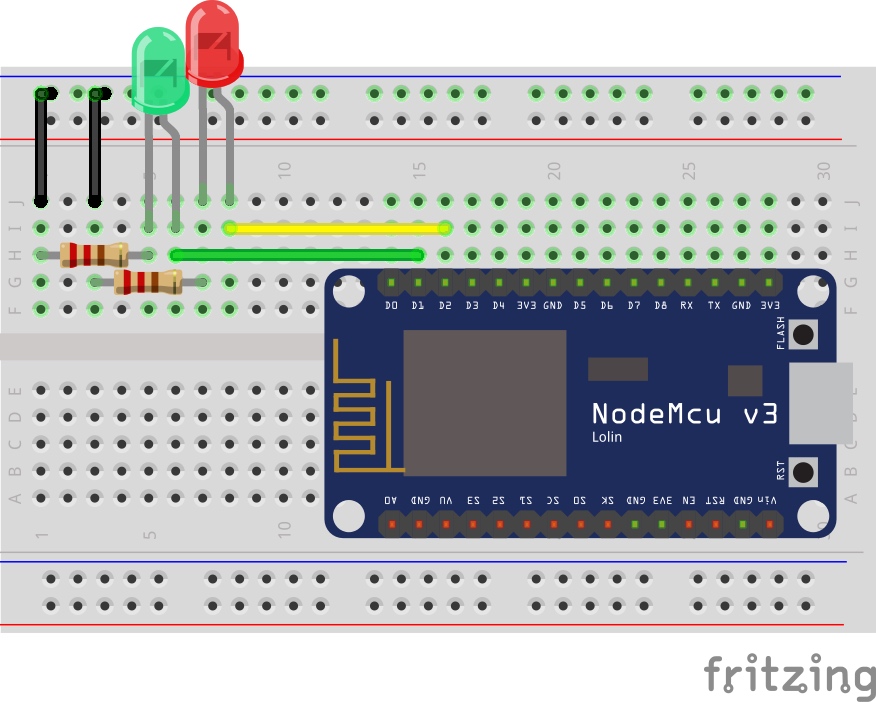
绿色和红色LED的正极分别连接到NodeMCU的数字引脚1和2,而它们的负极通过220欧姆电阻接地,以限制流过LED的电流量。完成原理图后,我们现在可以转到项目的代码。
编写程序
编程NodeMCU的最简单方法之一是通过Arduino IDE。但是,这需要通过安装NodeMCU的板支持文件来设置Arduino IDE。如果您是第一次使用Arduino IDE来对NodeMCU进行编程,则需要先进行此操作,然后再继续本教程。请按照此详细教程学习如何设置Arduino以对基于ESP8266的板进行编程。完成之后,我们现在可以开始编写代码了。本教程背后的主要驱动程序是ESP8266WiFi库。该库包含一些很酷的功能,用于在NodeMCU上实现基于WiFi的活动和项目。它包含我们创建WiFi接入点或与现有接入点连接以及创建服务器和客户端所需的全部功能,这对于今天的项目至关重要。这些库随附有用于Arduino的NodeMCU板文件,因此一旦安装了nodemcu开发板环境,就无需安装它们。如上所述,我们的目标是创建一个Web服务器,通过它可以控制NodeMCU的GPIO。应该通过与NodeMCU在同一网络上的任何设备上的浏览器访问Web服务器。这有点复杂,对于那些不了解HTML的人来说可能很难理解,但是我会尽力分解它。首先,像往常一样,我们包括用于代码的库,在本例中为ESP8266wifi库。
#include
接下来,添加NodeMCU将连接到的WiFi接入点的凭据。确保用户名和密码在双引号之间。我们还指定系统将通过其进行通信的端口,并创建一个变量来保存请求。
const char* ssid = "WIFI_SSID";
const char* password = "WIFI_PASSWORD";
WiFiServer server(80);// Set port to 80
String header; // This storees the HTTP request
接下来,我们声明将连接红色和绿色LED的Nodemcu的引脚,并创建变量以保存LED的状态。
int greenled = D1;
int redled = D2;
String greenstate = "off";// state of green LED
String redstate = "off";// state of red LED
完成此操作后,我们转到void setup()函数。我们首先初始化串行监视器(稍后将用于调试),并将LED连接到的引脚的pinModes设置为输出。然后,我们将引脚设置为“低”,以确保系统以中性状态启动。
void setup() {
  Serial.begin(115200);
 // Set the pinmode of the pins to which the LEDs are connected and turn them low to prevent flunctuations
  pinMode(greenled, OUTPUT);
  pinMode(redled, OUTPUT);
  digitalWrite(greenled, LOW);
  digitalWrite(redled, LOW);
接下来,我们使用凭据作为WiFi.begin()函数的参数连接到访问点,并使用WiFi.status()函数检查连接是否成功。
WiFi.begin(ssid, password);
Serial.print("Connecting to ");
Serial.println(ssid);
while (WiFi.status() != WL_CONNECTED) {
  delay(500);
  Serial.print(".");
}
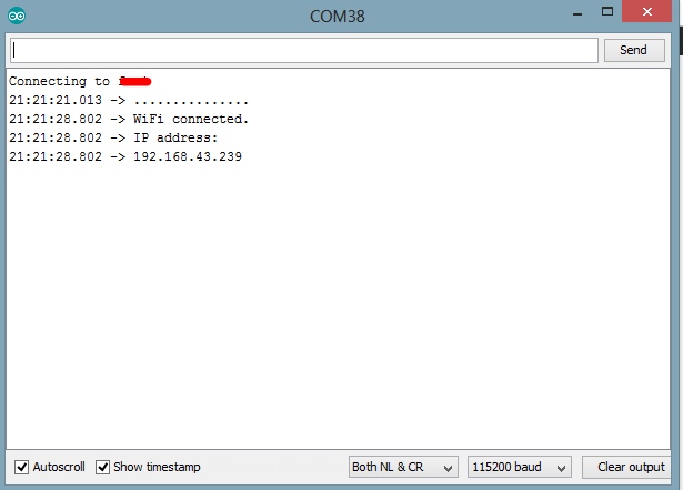
如果连接成功,则会在串行监视器上打印文本以表明这一点,并且还会显示Web服务器的IP地址。该IP地址成为服务器的网址,并且将在同一网络上的任何Web浏览器中输入该IP地址以访问服务器。
Serial.println("");
  Serial.println("WiFi connected.");
  Serial.println("IP address: ");
  Serial.println(WiFi.localIP());// this will display the Ip address of the Pi which should be entered into your browser
完成此操作后,我们使用server.begin()函数启动服务器,然后进入void loop()函数。
server.begin();
该void loop()函数是大部分的工作已经完成。我们首先使用server.available()函数来侦听客户端(Web浏览器)的传入连接。当客户端可用且已连接时,我们会读取客户端请求并发送标头作为响应。
WiFiClient client = server.available();   // Listen for incoming clientsif (client) {                             // If a new client connects,
    String currentLine = "";                // make a String to hold incoming data from the clientwhile (client.connected()) {            // loop while the client's connectedif (client.available()) {             // if there's bytes to read from the client,char c = client.read();             // read a byte, then
        Serial.write(c);                    // print it out the serial monitor
        header += c;
        if (c == 'n') {                    // if the byte is a newline character// if the current line is blank, you got two newline characters in a row.// that's the end of the client HTTP request, so send a response:if (currentLine.length() == 0) {
            // HTTP headers always start with a response code (e.g. HTTP/1.1 200 OK)// and a content-type so the client knows what's coming, then a blank line:
            client.println("HTTP/1.1 200 OK");
            client.println("Content-type:text/html");
            client.println("Connection: close");
            client.println();
接下来,我们检查客户的请求是否指示网页上的按钮按下,以从绿色LED开始“打开/关闭”任何引脚。如果请求指示“打开”,则该引脚变为高电平,状态变量相应更新,反之亦然。
// turns the GPIOs on and offif (header.indexOf("GET /green/on") >= 0) {
             Serial.println("green on");
             greenstate = "on";
             digitalWrite(greenled, HIGH);
           } else if (header.indexOf("GET /green/off") >= 0) {
             Serial.println("green off");
             greenstate = "off";
             digitalWrite(greenled, LOW);
           } else if (header.indexOf("GET /red/on") >= 0) {
             Serial.println("red on");
             redstate = "on";
             digitalWrite(redled, HIGH);
           } else if (header.indexOf("GET /red/off") >= 0) {
             Serial.println("red off");
             redstate = "off";
             digitalWrite(redled, LOW);
           }
接下来,我们创建将在用户与之交互时由NodeMCU显示和更新的网页。关键功能是Client.println()函数,该函数用于将HTML脚本逐行发送到客户端(浏览器)。我们首先使用“ doctype”来表明接下来要打印的文本是HTML行。
client.println("");
接下来,我们添加以下行以使网页响应,无论使用何种浏览器。
client.println("");
我们还向客户端添加了一些CSS,以使页面易于使用。您可以对其进行编辑以添加自己的颜色,字体样式等。
client.println("");
接下来,网页标题随按钮一起发送,按钮根据LED的当前状态被设置为打开或关闭。如果当前状态为“开”,则显示为关闭,反之亦然。
client.println("
ESP8266 Web Server

");
// Display current state, and ON/OFF buttons for GPIO 5
client.println("
green - State " + greenstate + "

");
// If the green LED is off, it displays the ON button
if (greenstate == "off") {
  client.println("
ON

");
} else {
  client.println("
OFF

");
}

// Display current state, and ON/OFF buttons for GPIO 4
client.println("
red - State " + redstate + "

");
// If the red LED is off, it displays the ON button
if (redstate == "off") {
  client.println("
ON

");
} else {
  client.println("
OFF
");
}
client.println("");
接下来,我们关闭连接,循环再次结束。
// Clear the header variable
header = "";
// Close the connection
client.stop();
Serial.println("Client disconnected.");
Serial.println("");
该项目的完整代码如下所示,也可以在本教程结尾的下载部分下下载。
#include

// Add wifi access point credentiaals
const char* ssid     = "WIFI_SSID";
const char* password = "WIFI_PASSWORD";

WiFiServer server(80);// Set port to 80


String header; // This storees the HTTP request

// Declare the pins to which the LEDs are connected
int greenled = D1;
int redled = D2;

String greenstate = "off";// state of green LED
String redstate = "off";// state of red LED


void setup() {
  Serial.begin(115200);
 // Set the pinmode of the pins to which the LEDs are connected and turn them low to prevent flunctuations
  pinMode(greenled, OUTPUT);
  pinMode(redled, OUTPUT);
  digitalWrite(greenled, LOW);
  digitalWrite(redled, LOW);
  //connect to access point
  WiFi.begin(ssid, password);
  Serial.print("Connecting to ");
  Serial.println(ssid);
  while (WiFi.status() != WL_CONNECTED) {
    delay(500);
    Serial.print(".");
  }
  // Print local IP address and start web server
  Serial.println("");
  Serial.println("WiFi connected.");
  Serial.println("IP address: ");
  Serial.println(WiFi.localIP());// this will display the Ip address of the Pi which should be entered into your browser
  server.begin();
}

void loop(){
  WiFiClient client = server.available();   // Listen for incoming clients

  if (client) {                             // If a new client connects,
    String currentLine = "";                // make a String to hold incoming data from the clientwhile (client.connected()) {            // loop while the client's connectedif (client.available()) {             // if there's bytes to read from the client,
        char c = client.read();             // read a byte, then
        Serial.write(c);                    // print it out the serial monitor
        header += c;
        if (c == 'n') {                    // if the byte is a newline character// if the current line is blank, you got two newline characters in a row.// that's the end of the client HTTP request, so send a response:if (currentLine.length() == 0) {
            // HTTP headers always start with a response code (e.g. HTTP/1.1 200 OK)// and a content-type so the client knows what's coming, then a blank line:
            client.println("HTTP/1.1 200 OK");
            client.println("Content-type:text/html");
            client.println("Connection: close");
            client.println();

            // turns the GPIOs on and offif (header.indexOf("GET /green/on") >= 0) {
              Serial.println("green on");
              greenstate = "on";
              digitalWrite(greenled, HIGH);
            } else if (header.indexOf("GET /green/off") >= 0) {
              Serial.println("green off");
              greenstate = "off";
              digitalWrite(greenled, LOW);
            } else if (header.indexOf("GET /red/on") >= 0) {
              Serial.println("red on");
              redstate = "on";
              digitalWrite(redled, HIGH);
            } else if (header.indexOf("GET /red/off") >= 0) {
              Serial.println("red off");
              redstate = "off";
              digitalWrite(redled, LOW);
            }

            // Display the HTML web page
            client.println("");
            client.println("");
            client.println("");
            // CSS to style the on/off buttons // Feel free to change the background-color and font-size attributes to fit your preferences
            client.println("");

            // Web Page Heading
            client.println("
ESP8266 Web Server

");

            // Display current state, and ON/OFF buttons for GPIO 5
            client.println("
green - State " + greenstate + "

");
            // If the green LED is off, it displays the ON button       if (greenstate == "off") {
              client.println("
ON

");
            } else {
              client.println("
OFF

");
            }

            // Display current state, and ON/OFF buttons for GPIO 4
            client.println("
red - State " + redstate + "

");
            // If the red LED is off, it displays the ON button       if (redstate == "off") {
              client.println("
ON

");
            } else {
              client.println("
OFF
");
            }
            client.println("");

            // The HTTP response ends with another blank line
            client.println();
            // Break out of the while loopbreak;
          } else { // if you got a newline, then clear currentLine
            currentLine = "";
          }
        } else if (c != 'r') {  // if you got anything else but a carriage return character,
          currentLine += c;      // add it to the end of the currentLine
        }
      }
    }
    // Clear the header variable
    header = "";
    // Close the connection
    client.stop();
    Serial.println("Client disconnected.");
    Serial.println("");
  }
}
演示结果
将代码上传到您的NodeMCU。确保按照原理图部分所述连接所有组件。上载代码后,打开串行监视器,您应该看到显示了Web服务器的IP地址,如下所示。
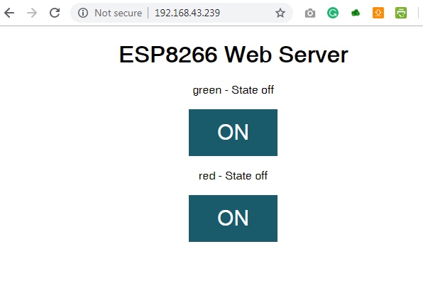
复制IP地址并粘贴到与NodeMCU连接到同一网络的设备上的Web浏览器中。您应该会看到网页,并且能够通过单击按钮来切换LED。
本教程就这样,谢谢阅读。
如上所述,本教程可作为复杂Web服务器和IoT解决方案的构建块。你会建造什么?如果您对今天的教程有任何疑问,请随时通过评论栏分享。


Awesome post! Keep up the great work! 🙂
求助!为什么我打开串口监视器只能看到一直增加的点
wifi网络连接不上,换个网试试
打开串口监视器后什么也不显示
看看波特率对不对
我复制下来的编译总是报错
下载源文件就好了