
释放双眼,带上耳机,听听看~!
简介
Lora是一种远距离传输的协议,在这个项目中,我们尝试与XL1276-D01 LoRa(433MHz)进行点对点连接,我们使用NodeMCU作为主控板。
提示:使用xl1278也可以。
在这个项目中,将包含发送器和接收器两个部分。
步骤一 材料清单
硬件:
- Nodemcu开发板*2
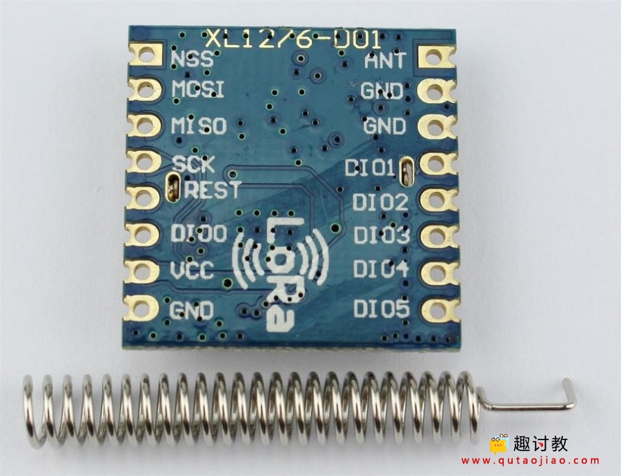
- XL1276-D01 LoRa模块*2或xl1278
- 若干杜邦线
- 面包板
软件:
- Arduino IDE
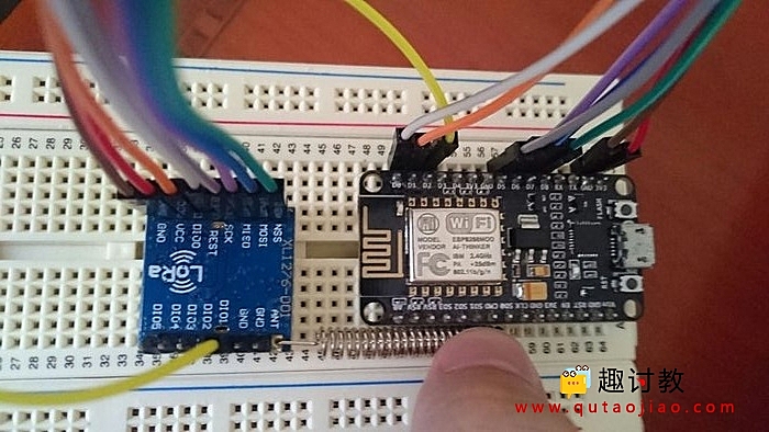
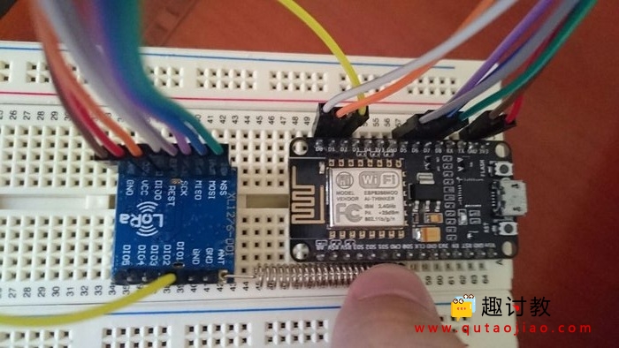
步骤二 硬件搭建
- ANT =>天线焊接
- GND => GND
- DIO1 => D2 / GPIO 4
- VCC => 3.3V
- DIO0 => D1 / GPIO 5
- RESET => D0 / GPIO 16
- SCK => D5 / GPIO 14
- MISO => D6 / GPIO 12
- MOSI => D7 / GPIO 13
- NSS => D8 / GPIO 15
发送器和接收器部分的连接与上面的引脚定义中所示的相同。
步骤四 开始编程
对于传输和接收,我们需要两个Arduino IDE同时运行。因此,我们需要打开两个Arduino IDE,最好是在不同的盘里面的软件,这样的目的是用两个不同的串口监视器。同时运行两个并将代码复制到Arduino IDE。
在编译代码之前,需要先下载LORA1276的库文件,下载地址:
发送器和接收器的完整代码如下:
发送器代码:
#include "SX1278.h"
#include

#define LORA_MODE  4
#define LORA_CHANNEL  CH_6_BW_125
#define LORA_ADDRESS  2

#define LORA_SEND_TO_ADDRESS  4

#define LORA_LED  9

int e;

char message1 [] = "Packet 1, wanting to see if received packet is the same as sent packet";
char message2 [] = "Packet 2, broadcast test";

void setup()
{
  pinMode(LORA_LED, OUTPUT);

  // Open serial communications and wait for port to open:
  Serial.begin(9600);

  // Print a start message
  Serial.println(F("sx1278 module and Arduino: send two packets (One to an addrees and another one in broadcast)"));

  // Power ON the moduleif (sx1278.ON() == 0) {
    Serial.println(F("Setting power ON: SUCCESS "));
  } else {
    Serial.println(F("Setting power ON: ERROR "));
  }

  // Set transmission mode and print the result if (sx1278.setMode(LORA_MODE) == 0) {
    Serial.println(F("Setting Mode: SUCCESS "));
  } else {
    Serial.println(F("Setting Mode: ERROR "));
  }

  // Set headerif (sx1278.setHeaderON() == 0) {
    Serial.println(F("Setting Header ON: SUCCESS "));
  } else {
    Serial.println(F("Setting Header ON: ERROR "));
  }

  // Select frequency channelif (sx1278.setChannel(LORA_CHANNEL) == 0) {
    Serial.println(F("Setting Channel: SUCCESS "));
  } else {
    Serial.println(F("Setting Channel: ERROR "));
  }

  // Set CRCif (sx1278.setCRC_ON() == 0) {
    Serial.println(F("Setting CRC ON: SUCCESS "));
  } else {
    Serial.println(F("Setting CRC ON: ERROR "));
  }

  // Select output power (Max, High, Intermediate or Low)if (sx1278.setPower('M') == 0) {
    Serial.println(F("Setting Power: SUCCESS "));
  } else {
    Serial.println(F("Setting Power: ERROR "));
  }

  // Set the node address and print the resultif (sx1278.setNodeAddress(LORA_ADDRESS) == 0) {
    Serial.println(F("Setting node address: SUCCESS "));
  } else {
    Serial.println(F("Setting node address: ERROR "));
  }

  // Print a success message
  Serial.println(F("sx1278 configured finished"));
  Serial.println();
}

void loop(void)
{
  // Send message1 and print the result
  e = sx1278.sendPacketTimeout(LORA_SEND_TO_ADDRESS, message1);
  Serial.print(F("Packet sent, state "));
  Serial.println(e, DEC);

  if (e == 0) {
      digitalWrite(LORA_LED, HIGH);
      delay(500);
      digitalWrite(LORA_LED, LOW);
  }

  delay(4000);

  // Send message2 broadcast and print the result
  e = sx1278.sendPacketTimeout(0, message2);
  Serial.print(F("Packet sent, state "));
  Serial.println(e, DEC);

  if (e == 0) {
      digitalWrite(LORA_LED, HIGH);
      delay(500);
      digitalWrite(LORA_LED, LOW);
  }

  delay(4000);
}
接收器代码:
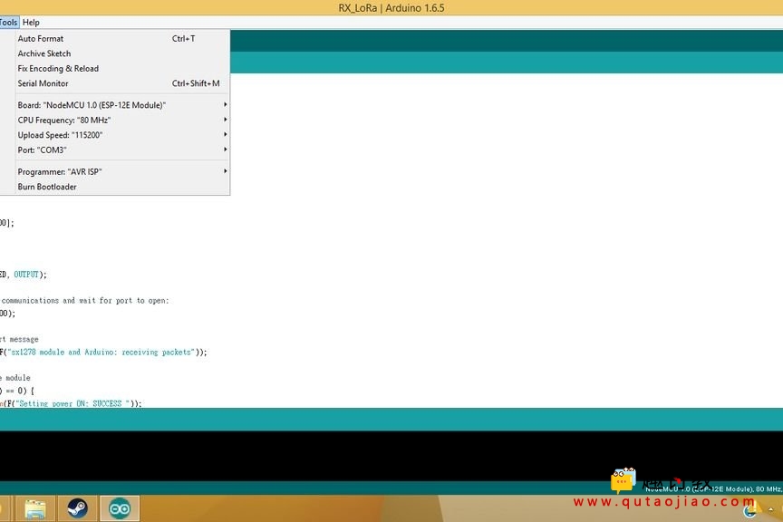
当你编译时,请记住在“工具”选项卡中将开发板设置更改为NodeMCU,如图所示。完成上传后,打开每侧的串行监视器。您将首先看到配置设置。完成所有配置后,发送器将开始发送消息,您可以在接收器看到收到的消息。