
释放双眼,带上耳机,听听看~!
简介
在这个项目中,我将描述如何将Ublox 6m GPS模块和OLED显示器连接到NodeMCU或ESP8266-12e wifi模块,以显示您当前的GPS位置和其他信息。你还可以通过一些额外的编程,使用它来使用esp8266上的wifi将您的GPS位置发送到互联网,并将其上传到中国移动ONENET或其他MQTT云服务器。
步骤一 材料准备
硬件准备:
- Nodemcu开发板(或ESP8266 – e12 wifi模块)×1
- OLED显示屏×1
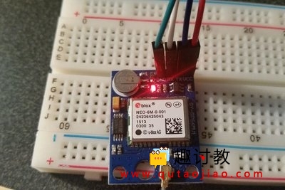
- Ublox 6m GPS模块或类似型号×1
- 面包板×1
- 杜邦线若干
软件准备:
- Arduino IDE
步骤二 电路搭建
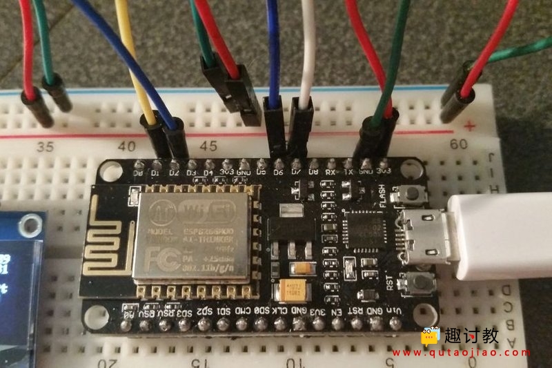
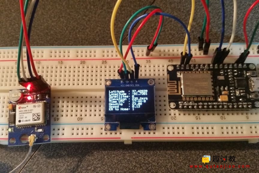
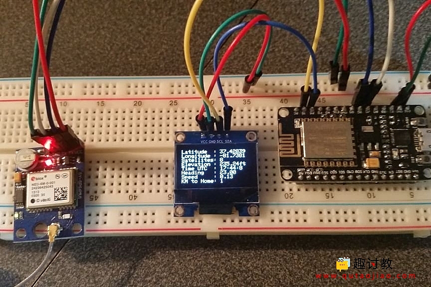
- 首先将ESP8266插在面包板上
- 将nodemcu的GND和VCC连接到面包板的电源和接地导轨(-和+)。
- 将GPS 和 Oled Display 的GND和VCC连接到面包板的电源和接地孔(接地 – ),VCC是(红色+)
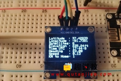
- 将Oled显示器的SCL引脚连接到nodemcu D1引脚(图中的黄线),并将Oled显示器的SDA引脚连接到D2引脚(图中的蓝线)这些是I2C通信连接线。
- 将GPS的TX引脚连接到nodemcu的D6引脚(蓝线),并将GPS的RX引脚连接到nodemcu的D7引脚(白线)这些是串行通信引脚。您可以选择任何您喜欢的数据引脚,但您还必须在代码中进行必要的更改。
步骤三 编写程序
在编写程序之前,你需要用到一个GPS的库文件,你必须下载库文件才能编译成功,库文件下载地址:
除此以外,你还需要安装一个SSD1306的库文件,下载地址如下:
万事俱备,只欠东风了,开始编程吧。。。。
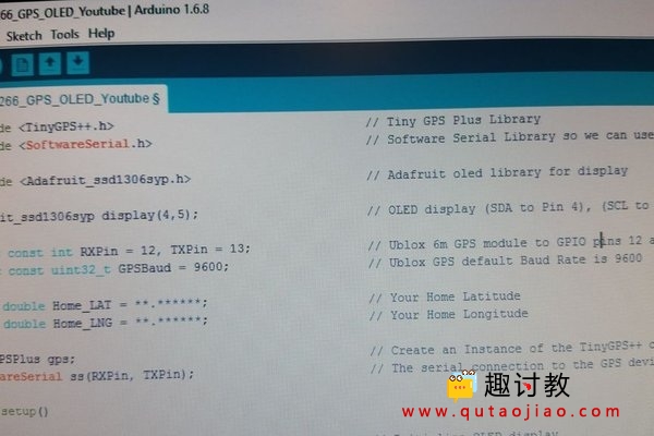
打开Arduino IDE开始编写程序:
#include <TinyGPS++.h> // Tiny GPS Plus Library
#include <SoftwareSerial.h> // Software Serial Library so we can use other Pins for communication with the GPS module

#include <Adafruit_ssd1306syp.h> // Adafruit oled library for display
Adafruit_ssd1306syp display(4,5); // OLED display (SDA to Pin 4), (SCL to Pin 5)

static const int RXPin = 12, TXPin = 13; // Ublox 6m GPS module to pins 12 and 13
static const uint32_t GPSBaud = 9600; // Ublox GPS default Baud Rate is 9600

const double Home_LAT = 32.38686; // Your Home Latitude
const double Home_LNG = 51.40899; // Your Home Longitude

TinyGPSPlus gps; // Create an Instance of the TinyGPS++ object called gps
SoftwareSerial ss(RXPin, TXPin); // The serial connection to the GPS device

void setup()
{
display.initialize(); // Initialize OLED display
display.clear(); // Clear OLED display
display.setTextSize(1); // Set OLED text size to small
display.setTextColor(WHITE); // Set OLED color to White
display.setCursor(0,0); // Set cursor to 0,0
display.println("GPS example");
display.println(TinyGPSPlus::libraryVersion());
display.update(); // Update display
delay(1500); // Pause 1.5 seconds
ss.begin(GPSBaud); // Set Software Serial Comm Speed to 9600
}

void loop()
{
display.clear();
display.setCursor(0,0);
display.print("Latitude : ");
display.println(gps.location.lat(), 5);
display.print("Longitude : ");
display.println(gps.location.lng(), 4);
display.print("Satellites: ");
display.println(gps.satellites.value());
display.print("Elevation : ");
display.print(gps.altitude.feet());
display.println("ft");
display.print("Time UTC : ");
display.print(gps.time.hour()); // GPS time UTC
display.print(":");
display.print(gps.time.minute()); // Minutes
display.print(":");
display.println(gps.time.second()); // Seconds
display.print("Heading : ");
display.println(gps.course.deg());
display.print("Speed : ");
display.println(gps.speed.mph());

unsigned long Distance_To_Home = (unsigned long)TinyGPSPlus::distanceBetween(gps.location.lat(),gps.location.lng(),Home_LAT, Home_LNG);
display.print("KM to Home: "); // Have TinyGPS Calculate distance to home and display it
display.print(Distance_To_Home);
display.update(); // Update display
delay(200);

smartDelay(500); // Run Procedure smartDelay

if (millis() > 5000 && gps.charsProcessed() < 10)
display.println(F("No GPS data received: check wiring"));
}

static void smartDelay(unsigned long ms) // This custom version of delay() ensures that the gps object is being "fed".
{
unsigned long start = millis();
do
{
while (ss.available())
gps.encode(ss.read());
} while (millis() - start < ms);
}
步骤四 验证结果