介绍
LCD(液晶显示器)用于显示嵌入式系统中的状态或参数。
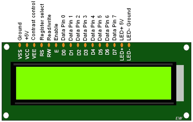
LCD 16×2是16引脚器件,具有8个数据引脚(D0-D7)和3个控制引脚(RS,RW,EN)。其余5个引脚用于LCD的电源和背光。
控制引脚可帮助我们在命令模式或数据模式下配置LCD。它们还有助于配置读取模式或写入模式以及何时进行读取或写入。
LCD 16×2可以在4位模式或8位模式下使用,具体取决于应用的要求。为了使用它,我们需要在命令模式下向LCD发送某些命令,一旦根据我们的需要配置LCD,我们就可以在数据模式下发送所需的数据。

16×2 LCD显示屏
4位模式
- 在4位模式下,数据/命令以4位(半字节)格式发送。
- 为此,首先发送高4位,然后发送低4位数据/命令。
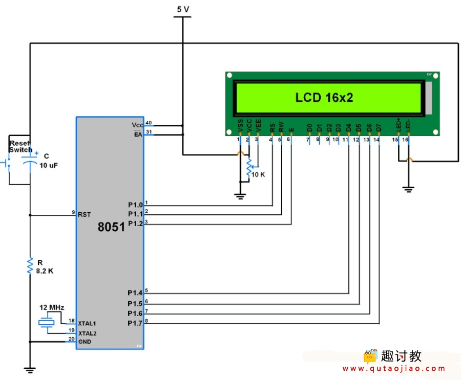
- 只有4个LCD的16个数据(D4-D7)引脚连接到微控制器,其他控制引脚RS(寄存器选择),RW(读/写),E(启用)连接到控制器的其他GPIO引脚。
- 因此,由于这种连接,我们可以减少四个GPIO引脚,可用于其他应用。
接口图

LCD 16×2接口,带8051
编写LCD16x2 4位模式方法
初始化
- 等待15ms,开启LCD16x2的初始化时间。
- 发送0x02命令,以4位模式初始化LCD 16×2。
- 发送0x28命令,以2行,4位模式和5×8点配置LCD。
- 发送任何Display ON命令(0x0E,0x0C)
- 发送0x06命令(增量光标)
void LCD_Init (void)		/* LCD Initialize function */
{
	delay(20);		/* LCD Power ON Initialization time >15ms */
	LCD_Command (0x02);	/* 4bit mode */
	LCD_Command (0x28);	/* Initialization of 16X2 LCD in 4bit mode */
	LCD_Command (0x0C);	/* Display ON Cursor OFF */
	LCD_Command (0x06);	/* Auto Increment cursor */
	LCD_Command (0x01);	/* Clear display */
	LCD_Command (0x80);	/* Cursor at home position */
}
现在我们成功初始化了LCD,它已准备好以4位模式接受数据显示。
要将命令/数据发送到16×2 LCD,我们必须发送更高的半字节,然后是低半字节。由于16×2 LCD的D4-D7引脚作为数据引脚连接,我们必须在发送之前将低半字节向右移动4。
命令写入功能
- 首先,发送更高的半字节命令。
- 使RS引脚为低电平,RS = 0(命令寄存器)
- 使RW引脚为低电平,RW = 0(写操作)或将其连接到地。
- 在启用(E)时给出高到低脉冲。
- 发送低位半字节命令。
- 在启用(E)时给出高到低脉冲。
void LCD_Command (char cmnd)	/* LCD16x2 command funtion */
{
	LCD_Port =(LCD_Port & 0x0F) | (cmnd & 0xF0);/* Send upper nibble */
	rs=0;			/* Command reg. */
	rw=0;			/* Write operation */
	en=1;
	delay(1);
	en=0;
	delay(2);

	LCD_Port = (LCD_Port & 0x0F) | (cmnd << 4);/* Send lower nibble */
	en=1;			/* Enable pulse */
	delay(1);
	en=0;
	delay(5);
}
数据写入功能
- 首先,发送更高的半字节数据。
- 使RS引脚为高电平,RS = 1(数据寄存器)
- 使RW引脚为低电平,RW = 0(写操作)或将其连接到地。
- 在启用(E)时给出高到低脉冲。
- 发送较低的半字节数据。
- 在启用(E)时给出高到低脉冲。
void LCD_Char (char char_data)	/* LCD data write function */
{
	LCD_Port =(LCD_Port & 0x0F) | (char_data & 0xF0);/* Send upper nibble */
	rs=1;			/* Data reg.*/
	rw=0;			/* Write operation*/
	en=1;
	delay(1);
	en=0;
	delay(2);

	LCD_Port = (LCD_Port & 0x0F) | (char_data << 4);/* Send lower nibble */
	en=1;			/* Enable pulse */
	delay(1);
	en=0;
	delay(5);

}
程序
/*
   LCD16x2 4 bit 8051 interface
   https://www.qutaojiao.com
*/


#include<reg51.h>

sfr LCD_Port=0x90;		/* P1 port as data port */
sbit rs=P1^0;			/* Register select pin */
sbit rw=P1^1;			/* Read/Write pin */
sbit en=P1^2;			/* Enable pin */


/* Function to provide delay Approx 1ms with 11.0592 Mhz crystal*/
void delay(unsigned int count)
{
     int i,j;
     for(i=0;i<count;i++)
     for(j=0;j<112;j++);
}

void LCD_Command (char cmnd)	/* LCD16x2 command funtion */
{
	LCD_Port =(LCD_Port & 0x0F) | (cmnd & 0xF0);/* Send upper nibble */
	rs=0;			/* Command reg. */
	rw=0;			/* Write operation */
	en=1;
	delay(1);
	en=0;
	delay(2);

	LCD_Port = (LCD_Port & 0x0F) | (cmnd << 4);/* Send lower nibble */
	en=1;			/* Enable pulse */
	delay(1);
	en=0;
	delay(5);
}

void LCD_Char (char char_data)  /* LCD data write function */
{
	LCD_Port =(LCD_Port & 0x0F) | (char_data & 0xF0);/* Send upper nibble */
	rs=1;  			/*Data reg.*/
	rw=0;  			/*Write operation*/
	en=1;
	delay(1);
	en=0;
	delay(2);

	LCD_Port = (LCD_Port & 0x0F) | (char_data << 4);/* Send lower nibble */
	en=1;  			/* Enable pulse */
	delay(1);
	en=0;
	delay(5);

}

void LCD_String (char *str)	/* Send string to LCD function */
{
	int i;
	for(i=0;str[i]!=0;i++)  /* Send each char of string till the NULL */
	{
		LCD_Char (str[i]);  /* Call LCD data write */
	}
}

void LCD_String_xy (char row, char pos, char *str)  /* Send string to LCD function */
{
	if (row == 0)
	LCD_Command((pos & 0x0F)|0x80);
	else if (row == 1)
	LCD_Command((pos & 0x0F)|0xC0);
	LCD_String(str);  	/* Call LCD string function */
}
余下程序:
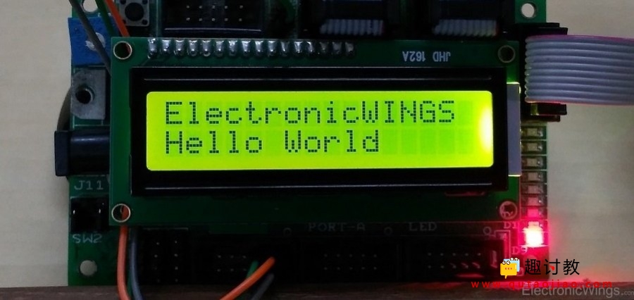
结果演示

本节课程序:


第一次没有成功