让我们用NodeMCU继续我们的IoT探索。在本教程中,我们将开发一个家庭气象站,在那里我们将显示室外信息,包括当天的温度和气候条件以及3天的预报。我们的站还将显示室内信息,如温度和空气湿度。
下面的方框图为我们提供了项目的总体概述。

第1步:物料清单
- NodeMCU ESP8266-12E
- 0.96寸 I2C IIC SPI串行128X64白色OLED LCD LED显示模块
- DHT22 AM2302温湿度传感器
- Mini BreadBoard
- 公母杜邦电缆
- 外部5V电源或电池
第2步:在NODEMCU上安装OLED
现在是时候安装OLED显示器,我们的老朋友SSD1306,其主要特点是:
- 显示尺寸:0.96“
- I2C IIC SPI串行
- 128X64
- 白色OLED LCD LED
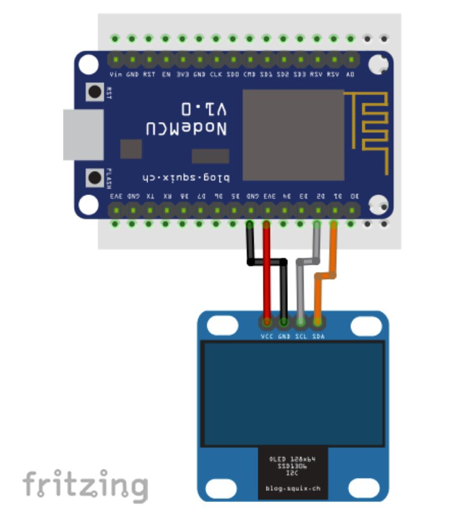
将OLED引脚连接到NodeMCU,如下面的电气图所示:
- SDA ==> D1(5)
- SCL * ==> D2(4)*您也可以在文本中找到“SDC”
- VCC ==> SSD1306可以直接从NodeMCU模块用5V(外部)或3.3V供电。
- GND ==> GND
连接完显示器后,让我们在Arduino IDE上下载并安装它的库。我们在之前的项目中使用了ACROBOT库版本,但这次我们将探索另一个:由Daniel Eichhorn开发的“用于SSD1306显示器的ESP8266 OLED驱动程序”(确保使用3.0.0或更高版本!)。
Bellow必须下载并安装在Arduino IDE上的库:
https://github.com/squix78/esp8266-oled-ssd1306
重新启动IDE后,应该已经安装了库。
该库支持I2C协议,使用内置的Wire.h库访问OLED显示器:
#include
#include "SSD1306.h"
SSD1306  display(ADDRESS, SDA, SDC);
让我们列出一些将与我们的OLED显示器一起使用的重要API。完整列表可以在上面提供的GITHub上建立。
A.显示控制:
void init(); // Initialise the display
void resetDisplay(void); // Cycle through the initialisation
void displayOn(void); // Turn the display on
void displayOff(void); // Turn the display offs
void clear(void); // Clear the local pixel buffer
void invertDisplay(void); // Inverted display mode
void normalDisplay(void); // Normal display mode
void setContrast(char contrast); // Set display contrast
void flipScreenVertically(); // Turn the display upside down
B.像素绘图
void setColor(OLEDDISPLAY_COLOR color); // Sets the color of all pixel operations
void setPixel(int16_t x, int16_t y); // Draw a pixel at given position
void drawLine(int16_t x0, int16_t y0, int16_t x1, int16_t y1); // Draw a line from pos 0 to pos 1
void drawHorizontalLine(int16_t x, int16_t y, int16_t length); // Draw a line horizontally
void drawVerticalLine(int16_t x, int16_t y, int16_t length); // Draw a lin vertically
void drawFastImage(int16_t x, int16_t y, int16_t width, int16_t height, const char *image); // Draw a bitmap in the internal image format
C.文本操作:
void drawString(int16_t x, int16_t y, String text);
// Write the text at given position
uint16_t getStringWidth(const char* text, uint16_t length);
// Returns the width of the const char* with the current font settings
uint16_t getStringWidth(String text);
// Convenience method for the const char version
void setTextAlignment(OLEDDISPLAY_TEXT_ALIGNMENT textAlignment);
// TEXT_ALIGN_LEFT, TEXT_ALIGN_CENTER, TEXT_ALIGN_RIGHT, TEXT_ALIGN_CENTER_BOTH
void setFont(const char* fontData);
// Sets the current font.

// Available default fonts: ArialMT_Plain_10, ArialMT_Plain_16, ArialMT_Plain_24
D.框架(“Ui库”)
Ui库用于提供一组基本的Ui元素,称为帧和叠加。Frame用于提供信息,默认行为是在定义的时间内显示Frame,然后移动到下一个(如“Pages”)。该库还提供了相应更新的指标。另一方面,覆盖是始终在相同位置显示的一条信息(例如,时钟)。
void init(); // Initialise the display
void setTargetFPS(uint8_t fps); //Configure the internal used target FPS
void enableAutoTransition(); //Enable automatic transition to next frame
void disableAutoTransition(); // Disable automatic transition to next frame.
void setAutoTransitionForwards(); // Set the direction if the automatic transitioning
void setAutoTransitionBackwards(); // Set the direction if the automatic transitioning
void setTimePerFrame(uint16_t time); //Set the approx. time a frame is displayed
void setTimePerTransition(uint16_t time); //Set the approx. time a transition will take
void setFrameAnimation(AnimationDirection dir); //Configure what animation is used to transition
void setFrames(FrameCallback* frameFunctions, uint8_t frameCount); //Add frame drawing functions
int8_t update();  // This needs to be called in the main loop
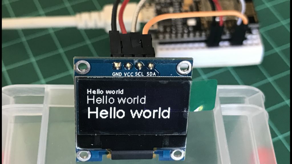
一旦安装了OLED本身及其库,让我们编写一个简单的“Hello World程序来测试它。在IDE上输入以下代码,结果应该是显示,如上图所示:
void init(); // Initialise the display
void setTargetFPS(uint8_t fps); //Configure the internal used target FPS
void enableAutoTransition(); //Enable automatic transition to next frame
void disableAutoTransition(); // Disable automatic transition to next frame.
void setAutoTransitionForwards(); // Set the direction if the automatic transitioning
void setAutoTransitionBackwards(); // Set the direction if the automatic transitioning
void setTimePerFrame(uint16_t time); //Set the approx. time a frame is displayed
void setTimePerTransition(uint16_t time); //Set the approx. time a transition will take
void setFrameAnimation(AnimationDirection dir); //Configure what animation is used to transition
void setFrames(FrameCallback* frameFunctions, uint8_t frameCount); //Add frame drawing functions
int8_t update();  // This needs to be called in the main loop
现在,上传草图:SSD1306SimpleDemo.ino,它是EXAMPLE的库的一部分。在运行代码之前,请更改OLED引脚连接:
// Initialise the OLED display using Wire library
SSD1306  display(0x3c, 5, 4);
第3步:获取室内数据
我们的NodeMCU正在与世界交流!所以,让我们给它一些真实的东西来展示!我们将安装数字温度/湿度型传感器。旧的和好的DHTxx(DHT11或DHT22)。该Adafruit的网站提供了有关这些传感器大量信息。贝娄,从那里检索到的一些信息:
概观
低成本的DHT温度和湿度传感器非常基本且速度慢,但对于想要进行基本数据记录的业余爱好者来说非常棒。DHT传感器由两部分组成,电容式湿度传感器和热敏电阻。内部还有一个非常基本的芯片可以进行模拟到数字转换,并在温度和湿度下发出数字信号。使用任何微控制器都可以轻松读取数字信号。
DHT11与DHT22
我们有两个版本的DHT传感器,它们看起来有点相似并具有相同的引脚排列,但具有不同的特性。以下是规格:
DHT11
- 超低成本
- 3至5V电源和I / O.
- 转换期间使用2.5mA最大电流(同时请求数据)
- 适用于20-80%湿度读数,准确度为5%
- 适用于0-50°C温度读数±2°C精度
- 采样率不超过1 Hz(每秒一次)
- 机身尺寸15.5mm x 12mm x 5.5mm
- 4个引脚,间距为0.1“
DHT22
- 低成本
- 3至5V电源和I / O.
- 转换期间使用2.5mA最大电流(同时请求数据)
- 适用于0-100%湿度读数,精度为2-5%
- 适用于-40至125°C的温度读数±0.5°C精度
- 采样率不超过0.5 Hz(每2秒一次)
- 体尺寸15.1mm x 25mm x 7.7mm
- 4个引脚,间距为0.1“
正如您所看到的,DHT22在更大的范围内更准确,更好。两者都使用单个数字引脚并且“缓慢”,因为您不能每秒查询一次(DHT11)或两次(DHT22)。
两个传感器都能正常工作,以便在我们的家庭气象站上显示室内信息。
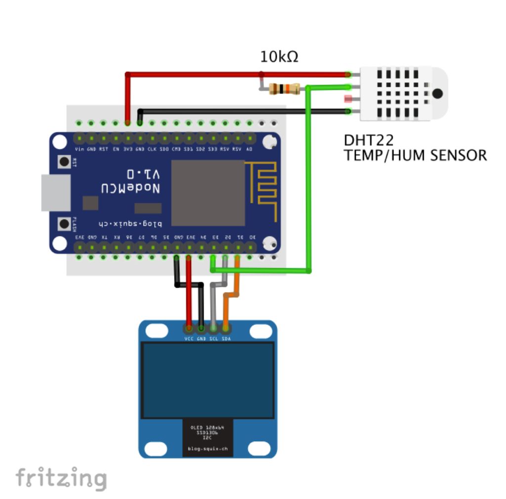
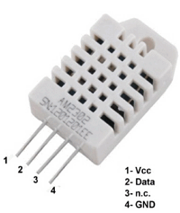
DHTxx有4个引脚(面向传感器,引脚1是最左边):
- VCC(我们可以从NodeMCU连接外部5V或3.3V);
- 数据输出;
- 未连接
- 地面。
通常,您将使用距离小于20米的传感器,数据和VCC引脚之间应连接一个10K欧姆的电阻。输出引脚将连接到NodeMCU引脚D3(参见上图)。
在我们的模块上安装传感器后,从Adafruit github存储库下载DHT库并将其安装在Arduino的库文件中。重新加载Arduino IDE后,应安装“DHT传感器库”。
让我们定义我们的传感器参数及其相关变量(我们将首先使用DHT22):
/* DHT22 */
#include "DHT.h"
#define DHTPIN D3
#define DHTTYPE DHT22
DHT dht(DHTPIN, DHTTYPE);
int localHum = 0;
int localTemp = 0;
现在,让我们创建一个函数来读取它的数据:
/***************************************************
* Get indoor Temp/Hum data
****************************************************/
void getDHT()
{
  float tempIni = localTemp;
  float humIni = localHum;
  localTemp = dht.readTemperature();
 /* for returning Fahrenheit use localTemp = dht.readTemperature(true) */
  localHum = dht.readHumidity();
  if (isnan(localHum) || isnan(localTemp))   // Check if any reads failed and exit early (to try again).
  {
    Serial.println("Failed to read from DHT sensor!");
    localTemp = tempIni;
    localHum = humIni;
    return;
  }
}
获得数据后,让我们将它们呈现在OLED显示屏上:
/***************************************************
* Draw Indoor Page
****************************************************/
void drawDHT()
{
  int x=0;
  int y=0;
  display.setFont(ArialMT_Plain_10);
  display.setTextAlignment(TEXT_ALIGN_LEFT);
  display.drawString(0 + x, 5 + y, "Hum");

  display.setFont(ArialMT_Plain_10);
  display.setTextAlignment(TEXT_ALIGN_LEFT);
  display.drawString(43 + x, y, "INDOOR");

  display.setFont(ArialMT_Plain_24);
  String hum = String(localHum) + "%";
  display.drawString(0 + x, 15 + y, hum);
  int humWidth = display.getStringWidth(hum);

  display.setFont(ArialMT_Plain_10);
  display.setTextAlignment(TEXT_ALIGN_LEFT);
  display.drawString(95 + x, 5 + y, "Temp");

  display.setFont(ArialMT_Plain_24);
  String temp = String(localTemp) + "°C";
  display.drawString(70 + x, 15 + y, temp);
  int tempWidth = display.getStringWidth(temp);
}
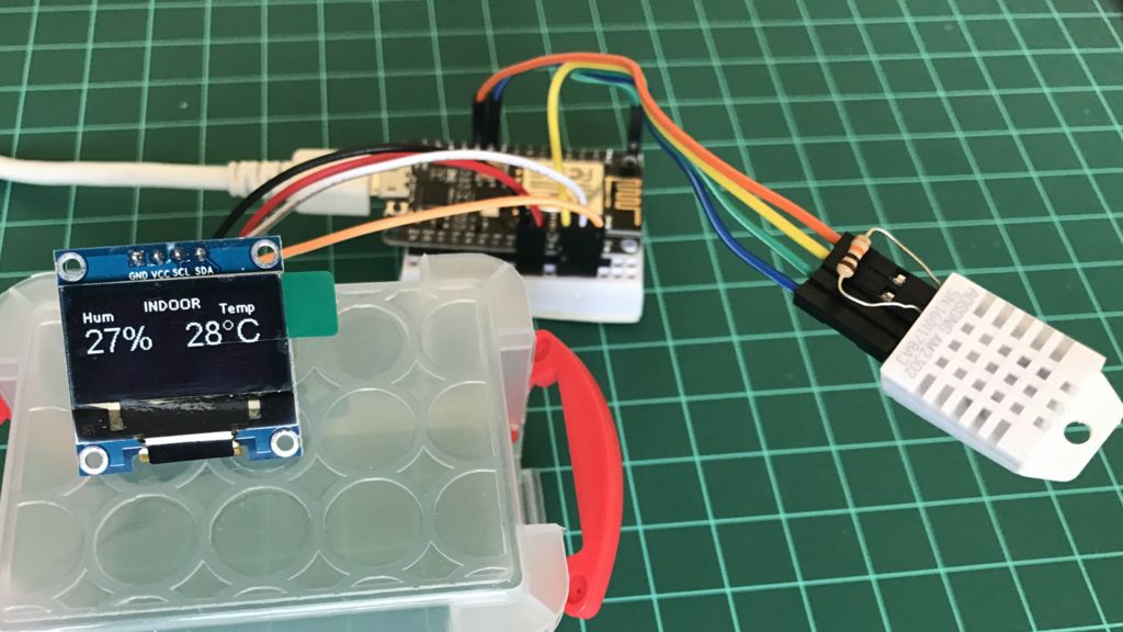
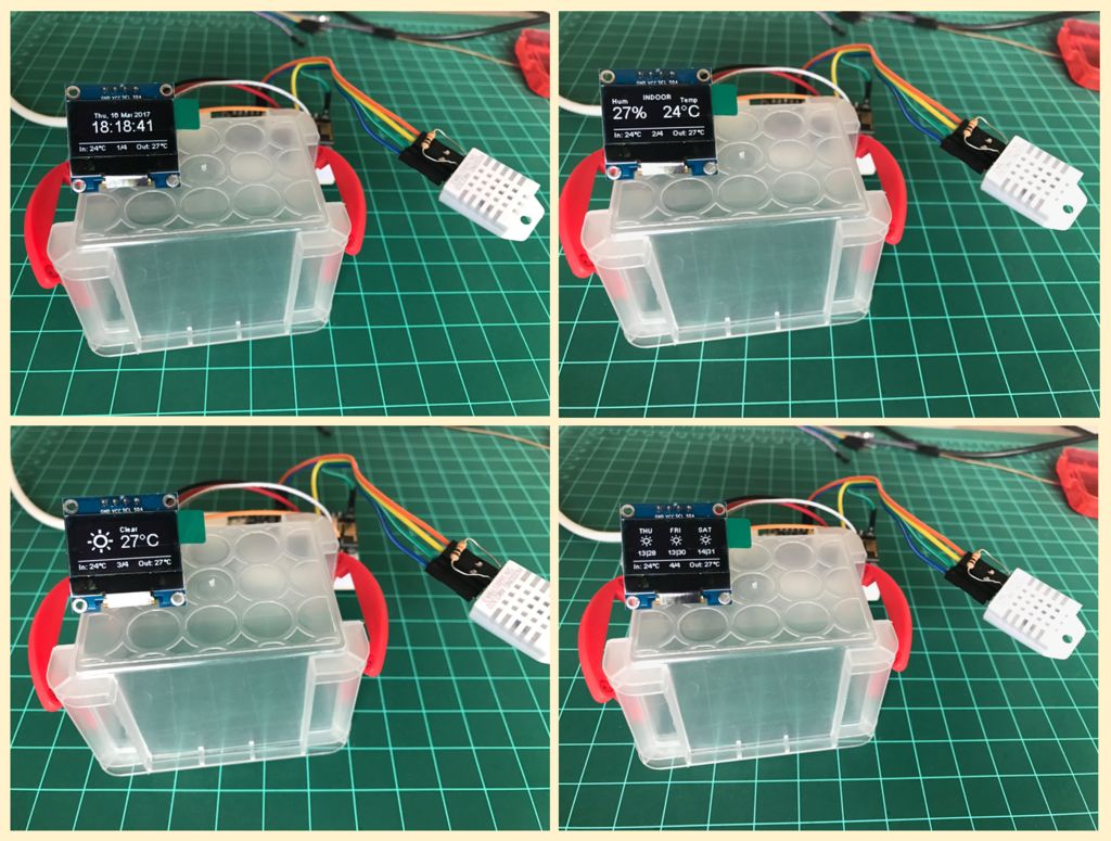
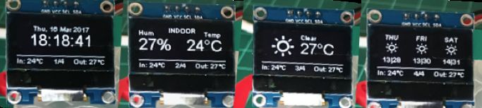
上面的照片显示了数据在显示屏上的显示方式。
您可以从我的GitHub:Home Weather Station室内代码下载完整的室内操作
或者使用下面的文件:
Home_Weather.ino
第4步:户外数据:天气地下服务
我们的室外天气数据将通过免费服务Weather Underground提供。您需要在其网站上创建一个帐户并获取Weather API密钥。按照下面的说明操作:
https://www.wunderground.com/weather/api
我们的气象站基于Daniel Eichhorn(@ squix78)所做的出色工作。按照他的GitHub上的说明获取适当的库。您至少需要安装以下库:
- Daniel Eichhorn气象站:https://github.com/squix78/esp8266-weather-station
- Daniel Eichhorn的Json Streaming Parser:https://github.com/squix78/json-streaming-parser
安装库并重新启动IDE后,从我的GitHub下载以下程序:
在Arduino IDE上加载代码后,打开“stationCredentials.h”并将虚拟数据替换为人员数据:
/* WIFI */
const char* WIFI_SSID = "YOUR SSID";
const char* WIFI_PWD = "YOUR PASSWORD";

/* Wunderground Settings */
const boolean IS_METRIC = true; // use false for Fahrenheit
const String WUNDERGRROUND_API_KEY = "YOUR KEY";
const String WUNDERGRROUND_LANGUAGE = "EN";
const String WUNDERGROUND_COUNTRY = "CL";
const String WUNDERGROUND_CITY = "Santiago";
请注意,我们将从W.Underground服务中检索的天气信息将与圣地亚哥(城市)和CL(国家:智利)有关。您还必须使用自己的城市数据进行更改。
就是这样!您的工作站必须现在正在运行,您可以在我上面的原型照片上看到。