
这篇文章演示了如何搭建一个Arduino以太网Web服务器,用于控制连接到灯的继电器。
您可以通过任何连接到相同网络的设备上的浏览器访问您的Web服务器。

注意:如果您对处理电源电压不够熟悉,但仍想尝试完成该项目,您可以将继电器模块替换为LED。代码和原理图非常相似。
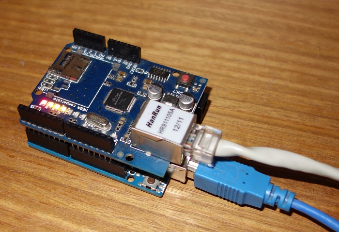
以太网扩展板
Arduino以太网扩展板简单地将您的Arduino连接到互联网。只需将此模块安装到Arduino板上,使用RJ45电缆连接到网络,然后按照几个简单的步骤通过Web控制您的项目。
注意:必须将以太网电缆从路由器连接到以太网扩展板。
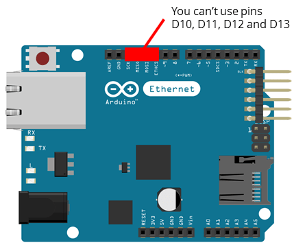
引脚使用
当Arduino连接到以太网扩展板时,不能使用10到13的数字引脚,因为它们用于在Arduino和以太网扩展板之间建立通信。
继电器模块
继电器是一种电动开关,可以打开或关闭,控制电流通过或不通过。继电器模块连接如下:
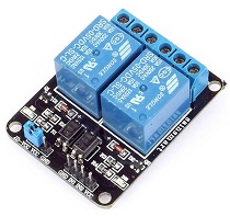
这个特殊的继电器模块带有两个继电器(那些蓝色立方体)。
关于电源电压,继电器有 3 种可能的连接:
- COM:公共引脚
- NO:常开 – 公共引脚和常开引脚之间没有接触。因此,当您触发继电器时,它会连接到 COM 引脚并为负载(在我们的例子中为灯)供电。
- NC:常闭 – 公共引脚和常闭引脚之间有接触。COM 和 NC 引脚之间始终存在接触,即使在继电器关闭时也是如此。当您触发继电器时,电路断开,并且没有向负载供电。
继电器和Arduino之间的连接非常简单:
所需零件
以下是此项目所需的组件的完整列表:
- Arduino UNO
- 以太网扩展板
- 继电器模块
- 灯线组
- 面包板
- 跳线
使用方法
将以下代码复制到Arduino IDE,在将其上传到Arduino板之前,请阅读下面的“配置网络”部分。
#include <SPI.h>
#include <Ethernet.h>

// Enter a MAC address and IP address for your controller below.
// The IP address will be dependent on your local network:
byte mac[] = {
  0xDE, 0xAD, 0xBE, 0xEF, 0xFE, 0xED };
IPAddress ip(192,168,1, 111);

// Initialize the Ethernet server library
// with the IP address and port you want to use
// (port 80 is default for HTTP):
EthernetServer server(80);

// Relay state and pin
String relay1State = "Off";
const int relay = 7;

// Client variables
char linebuf[80];
int charcount=0;

void setup() {
  // Relay module prepared
  pinMode(relay, OUTPUT);
  digitalWrite(relay, HIGH);

  // Open serial communication at a baud rate of 9600
  Serial.begin(9600);

  // start the Ethernet connection and the server:
  Ethernet.begin(mac, ip);
  server.begin();
  Serial.print("server is at ");
  Serial.println(Ethernet.localIP());
}

// Display dashboard page with on/off button for relay
// It also print Temperature in C and F
void dashboardPage(EthernetClient &client) {
  client.println("<!DOCTYPE HTML><html><head>");
  client.println("<meta name="viewport" content="width=device-width, initial-scale=1"></head><body>");
  client.println("<h3>Arduino Web Server - <a href="/">Refresh</a></h3>");
  // Generates buttons to control the relay
  client.println("<h4>Relay 1 - State: " + relay1State + "</h4>");
  // If relay is off, it shows the button to turn the output on
  if(relay1State == "Off"){
    client.println("<a href="/relay1on"><button>ON</button></a>");
  }
  // If relay is on, it shows the button to turn the output off
  else if(relay1State == "On"){
    client.println("<a href="/relay1off"><button>OFF</button></a>");
  }
  client.println("</body></html>");
}


void loop() {
  // listen for incoming clients
  EthernetClient client = server.available();
  if (client) {
    Serial.println("new client");
    memset(linebuf,0,sizeof(linebuf));
    charcount=0;
    // an http request ends with a blank line
    boolean currentLineIsBlank = true;
    while (client.connected()) {
      if (client.available()) {
       char c = client.read();
       //read char by char HTTP request
        linebuf[charcount]=c;
        if (charcount<sizeof(linebuf)-1) charcount++;
        // if you've gotten to the end of the line (received a newline
        // character) and the line is blank, the http request has ended,
        // so you can send a reply
        if (c == 'n' && currentLineIsBlank) {
          dashboardPage(client);
          break;
        }
        if (c == 'n') {
          if (strstr(linebuf,"GET /relay1off") > 0){
            digitalWrite(relay, HIGH);
            relay1State = "Off";
          }
          else if (strstr(linebuf,"GET /relay1on") > 0){
            digitalWrite(relay, LOW);
            relay1State = "On";
          }
          // you're starting a new line
          currentLineIsBlank = true;
          memset(linebuf,0,sizeof(linebuf));
          charcount=0;
        }
        else if (c != 'r') {
          // you've gotten a character on the current line
          currentLineIsBlank = false;
        }
      }
    }
    // give the web browser time to receive the data
    delay(1);
    // close the connection:
    client.stop();
    Serial.println("client disonnected");
  }
}
配置网络
看一下配置网络代码片段:
byte mac[] = {
0xDE, 0xAD, 0xBE, 0xEF, 0xFE, 0xED };
IPAddress ip(192,168,1,XXX);
重要提示:您实际上可能需要将以红色突出显示的变量替换为适合您网络的适当值,否则您的 Arduino 将无法与您的网络建立连接。
将以下行替换为可用且适合您的网络的 IP:
IPAddress ip(X, X, X, X);就我而言,我的 IP 范围是 192.168.1.X,使用软件 Angry IP Scanner,我知道 IP 192.168.1.111 在我的网络中可用,因为它在我的网络中没有任何具有完全相同 IP 地址的活动设备:
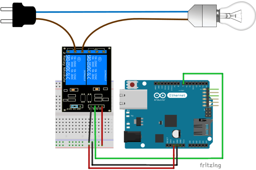
IPAddress ip(192, 168, 1, 111);连接图
按照下面的原理图连接电路:
示范
您的 Arduino Web 服务器如下图所示:
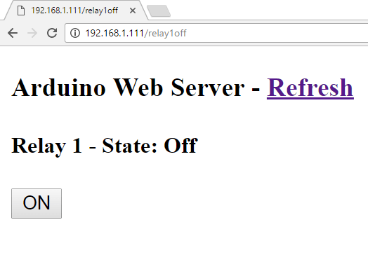
下面是一个演示,展示了你在这个项目结束时所拥有的内容:

总结
通过这个项目,您成功构建了一个Arduino Web服务器,用于控制继电器的开关。现在,您可以使用此项目来控制您想要的任何电子设备。